Backflow Test Equipment Used by Plumbers
Backflow prevention devices protect the public water supply from contaminated backflow. They can prevent diseases like dysentery, typhoid fever, and Legionnaire’s disease.
Testing backflow prevention devices is a legal requirement for some businesses and property owners. It involves closing valves, using gauges and watching for changes in water pressure. Plumbers Sarasota will take care of everything from shutting off the water to filing paperwork with the city.
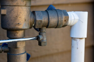
Test-cocks are small nozzles on backflow preventers that allow plumbers to access the water flowing through them for testing. They are important because they can help ensure that the backflow device works correctly and protects the potable water supply from contamination. Test-cocks are installed on all backflow devices, but they are especially useful for backflow testing because they provide access to the backflow assembly without requiring the use of a vacuum pump or air compressor. The test cocks can be opened or closed with the aid of a flathead screwdriver, but they are not designed to be used as bleed valves or drain valves.
The process of backflow testing begins with shutting off the downstream shut-off valve. Then, the plumber performs a visual inspection of the backflow device and the surrounding area to check for leaks and other problems. Next, the plumber will hook up the test kit hoses to the backflow device using the test cocks. The plumber must follow the specific procedure for the type of backflow mechanism and the orientation of the valve components.
For example, the Febco BF and Watts BR devices have four test cocks that can be opened or closed by using a flat tip screwdriver. The lower test cock should be turned to the vertical position and the higher one to the horizontal position. The handles should be at a 45 degree angle. Test-cocks that are not properly aligned or positioned may cause the test to fail.
Once the test cocks are open, the plumber can run a direction of flow test by opening test cock No. 4 and establishing flow. Then, they can close the test cocks and record the results. The USC 10th Edition Field Test Procedure goes further by adding steps to ensure that the relief valve is not exercised before recording the opening point of the test cocks. This is important because a prematurely exercising relief valve can cause the test assembly to fail.
The tester should also ensure that the pressure on the downstream side of the assembly is at atmospheric pressure before conducting a pressure test on the second check valve. Then, they can open test cock No. 4 and drop the pressure on the downstream side of the second check valve to atmospheric pressure. This will allow them to record the opening point of the test cocks.
Pressure gauges
Pressure gauges are used to measure the pressure of air or fluids in a system, commercial or industrial. They are mechanical instruments that do not require any external power source to operate. They are a vital part of the backflow testing equipment that plumbers use and must be carefully chosen for each job to ensure accurate readings. Pressure gauges are available in a variety of sizes, shapes and finishes to accommodate different applications. They can be made from a range of materials, such as stainless steel, aluminum and thermoplastic. The type of case that a gauge is housed in also impacts its performance. Some cases are solid front, while others feature a window.
Choosing the right gauge for each application requires a thorough understanding of the environment and media that it will be exposed to. Manufacturers offer a wide selection of gauges that are designed for corrosive chemicals and environments, different types of gases, as well as conditions that include impact, vibration and temperature extremes. They may also be constructed with different seals to enhance protection against contaminants.
The most common pressure gauge is the bourdon tube style, which features a flexible measuring element. This elastic element moves when there is a change in pressure, causing the movement of a connecting rod that is connected to the dial pointer. The precise mechanism inside the gauge converts this tube motion into a rotary movement to drive the pointer, indicating the pressure measurement on the dial.
Another consideration when selecting a gauge is its accuracy standards, which are designated as the percentage of the full scale or span. The higher the accuracy class, the less error tolerance it has. This is important because inaccurate gauges can lead to erroneous measurements and even malfunction of the entire test kit.
It is also important to note that a pressure gauge may start off with the proper accuracy when it is built, but over time and due to exposure to various factors, its accuracy can begin to drift. This is why it is important to regularly test and calibrate the pressure gauge.
Check valves
Check valves are essential for backflow testing and are commonly found in plumbing systems. They work by allowing fluids to flow freely in one direction but closing to prevent unwanted backflow. They can be used in a wide range of applications, including stopping drainage in fire sprinkler systems with elevation changes, preventing contamination from flowing back into the main water supply, and ensuring airflow direction in HVAC systems for indoor air quality.
There are several different configurations of check valves, but they all function the same way. They have a spring-loaded seal that is held against the valve seat by pressure. The internal flow path can be axial between the seal and the valve body, or it may go through passages within the poppet. The seal can be a disc, ball bearing, or another shape.
The design of the check valve is important because it must be able to open and close easily. It also needs to be able to resist high temperatures. In addition, it must be able to withstand high backpressure. This is important for protecting the system from contaminants, which can be backflowed from industrial equipment or chemicals.
In addition to their role in preventing backflow, check valves can help prevent damage to pipes and other equipment. In particular, they can prevent the phenomenon of water hammer, which occurs when a rapid change in velocity causes a valve to close quickly. This can cause a shock wave that damages pipe and equipment. A non-slam check valve can help prevent this by using a special design that ensures that the valve opens slowly and closes gently.
A check valve can be installed near the point of entry into a building’s water network to ensure that any backflow is prevented. It should also be installed in a location where it can be accessed for routine maintenance and inspection. This will ensure that the system is functioning properly and preventing any backflow from entering the city’s water supply. It’s also important to consult a professional plumber before installing a check valve. They can provide advice on the correct style and options for your application.
Relief valves
The relief valve is a vital component of a backflow testing system. It is designed to open and discharge water if there is a pressure override, such as when the first check valve fails. The valve will also open if the second check leaks or if the pressure past the 1st check is greater than the relief valve setting point. During testing, the valve is controlled by an electrical signal from the meter. This signal energizes solenoid C1 on the relief valve B. This opens the valve as the cylinder extends, slowing down the cylinder’s descent and preventing shock or bouncing. The circuit also de-energizes the solenoid when the cylinder reaches work, which closes prefill valve F and drops the cylinder’s rod end to tank pressure. The cylinder then retracts and the relief valve closes.
The design of a relief valve varies with the type of application and the pressure rating of the system. Some are based on the differential between inlet and outlet ports while others use a reference pressure to determine when the valve should open. The reference pressure can be the ambient pressure, a set pressure or an actual working pressure of the system. The valves are usually made of a steel or brass housing with inlet and outlet connections and a spring within the chamber that keeps a pressure plate in place sealing the discharge. A set valve nut or screw on the top of the housing can be used to set the desired pressure at which the relief valve should open.
When the inlet shut-off is opened, water travels past the first check and into a zone of reduced pressure between the two checks. This pressurizes the area behind the 1st check, and it also creates a higher pressure on the low pressure side of the elastic element in the relief valve. As this pressure increases, it will move the diaphragm and increase the value on the sensing line. This value will be greater than the relief valve setting point of 2.1 PSID.
Many backflow prevention assemblies have a vent port on the upstream side of the assembly body ahead of the 1st check. This is connected to a remote direct-acting relief valve, which can be connected to multiple remote reliefs. In these arrangements, each remote relief can be commanded to open at different pressures, giving the tester a choice of several preset or infinitely variable limits for a test.